- Lifting Drawing
- Lifting Calculation
- Lifting Simulation
3D Crane Design Service for Lifting Plan Requirements :
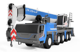
Executing heavy lifting operations demands meticulous planning considering key variables such as crane capacity, configuration, main boom length, jib rating, working radius, crane positioning, ground site conditions, and load dimensions. Utilizing 3D crane models provides superior spatial and visual clarity compared to conventional 2D drawings. 3D models significantly assist engineering teams in:
1, Visualizing crane positioning relative to the lifting site and surrounding structures
2. Verifying crane configurations and assembly setups
3. Checking operating working radius and boom angles
4. Evaluating critical clearances and potential obstruction clashes
5. Verifying counterweight tray layouts and tail-swing radius
Project Objectives
The primary objective is to deliver representative, highly accurate 3D crane models in accordance with technical data to support engineering and lifting plan requirements. Specific objectives include:
1. Delivering 3D crane models according to specified make, model, and capacity.
2. Configuring crane components according to exact lifting plan requirements.
3. Assisting spatial visualization of crane position relative to load and environment.
4. Enabling precise dimensional checks and physical clearance verification.
5. Supporting graphics generation for engineering reports and lifting plan submissions.
6. Providing complete technical documentation matching the defined scope.
Scope of Work
Decranes scope encompasses 3D modelling and crane configuration based on technical data provided by the Client. Scope components include:
1. Data Collection & Review
Review of technical documentation supplied by the Client, including: Crane Manufacturer, Model/Type, Nominal Capacity, Manufacturer Datasheet, Load Chart, Dimensional Drawings, Boom/Jib Specifications, Counterweight Tray Details, Outrigger/Crawler Specs, Configuration Data, and Supporting Site Drawings.
2. 3D Crane Modelling
3D modelling covers all primary crane components: Carrier/Crawler Base, Upper Structure, Superstructure, Main Boom, Jib Assembly, Counterweight Blocks, Outrigger Pads / Crawler Tracks, Hook Blocks, and Primary Lifting Attachments. Level of detail (LOD) is tailored for engineering and lifting plan visualization.
3. Crane Configuration
Configuring the 3D model according to specific operational parameters: Boom/Jib combination, Boom length, Counterweight arrangement, Outrigger spread, Working radius, and Boom angle.
4. Supporting Models
Where specified, supporting models can include representation of the lifted load, rigging accessories, hook block placement, working boundary area, clearance limits, structural obstacles, and foundation supports.
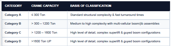
Crane Capacity Classification
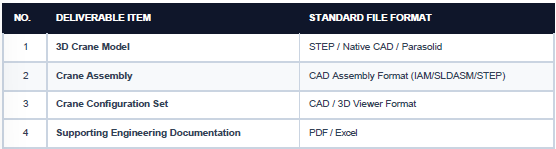
Deliverables